Race Engine Building: Critical Clearances & Tips
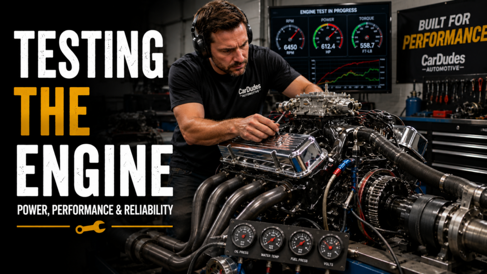
Race engine building is about much more than assembling high-performance parts. A reliable racing engine depends on precise measurements, correct clearances and matching every component to the engine’s intended RPM, horsepower and use.
Whether you’re working with a small-block or big-block V8, successful race engine building starts with the same fundamentals: measure carefully, verify every clearance and never assume one specification is right for every engine combination.
1. Race Engine Building: Main and Rod Bearing Clearances
Correct main and rod bearing clearance is critical in a performance or racing engine. The clearance must provide enough room for a stable oil film between the crankshaft journals and bearings without becoming so loose that oil pressure and oil-film control suffer.
A commonly used starting point is:
Journal Diameter × .001 = Approximate Oil Clearance
For example:
2.000-inch journal:
2.000 × .001 = .0020-inch clearance
2.500-inch journal:
2.500 × .001 = .0025-inch clearance
High-RPM, high-load and racing combinations may require different clearances depending on the crankshaft, bearing design, oil viscosity, operating temperature and intended use.
Measure—Don’t Guess
For precision engine building, install and torque the bearings in the main bore or connecting rod, then measure the bearing inside diameter with a dial bore gauge. Measure the crankshaft journals separately with a micrometer.
Installed Bearing I.D. − Crankshaft Journal Diameter = Actual Oil Clearance
Check every main and rod journal individually. Do not assume that because one journal measures correctly, the others will be identical.
Too little clearance can increase oil temperature and risk bearing damage. Excessive clearance can increase oil leakage, reduce oil-pressure control and compromise the oil film.
Always verify the final clearance against the specifications provided by the crankshaft and bearing manufacturer and the requirements of your particular engine combination.
2. Piston-to-Wall Clearance
Piston-to-wall clearance is especially important in a high-performance engine. Forged aluminum pistons expand as operating temperature increases, and the amount of clearance required depends on the piston alloy, design, bore size and intended use of the engine.
Do not use one piston-to-wall clearance specification for every forged piston.
2618 forged pistons generally require more operating clearance than lower-expansion piston designs, but the correct specification should always come from the manufacturer of the exact piston being installed.
Measure the Piston Correctly
Measure the cylinder bore with a dial bore gauge and the piston with a micrometer at the manufacturer’s specified gauge point—typically on the skirt and at a specified distance from the bottom of the piston.
Cylinder Bore Diameter − Piston Diameter = Piston-to-Wall Clearance
For example:
4.0300-inch finished cylinder bore
− 4.0255-inch piston diameter
= .0045-inch piston-to-wall clearance
This example demonstrates the calculation only. It is not a recommended clearance for every piston.
High-RPM racing, forced induction, nitrous and severe-duty applications can generate additional heat and may require additional clearance when specified by the piston manufacturer.
Too little clearance can cause piston scuffing or seizure as the piston expands. Excessive clearance can contribute to piston noise, poor ring stability and accelerated wear.
Always follow the piston manufacturer’s recommended measuring point and piston-to-wall clearance for your exact piston and engine combination.
3. Piston Ring Gapping
Piston Ring End Gap
Proper piston ring end gap is critical in a high-performance or racing engine. As combustion temperatures rise, the piston rings expand. If the end gap is too tight, the ends of the ring can eventually touch—or “butt”—which can damage the rings, pistons and cylinder walls.
A common method for establishing a starting point is:
Cylinder Bore × Recommended Ring-Gap Factor = Ring End Gap
For example, with a 4.250-inch bore:
Street Performance:
4.250 × .0045 = .0191-inch top-ring gap
Drag/Racing:
4.250 × .0055 = .0234-inch top-ring gap
Turbo/Nitrous Race Application:
4.250 × .0065 = .0276-inch top-ring gap
These numbers are general examples—not universal specifications. Ring material, piston design, horsepower level, fuel, cylinder temperature, boost, nitrous and intended use can all affect the required clearance.
Always use the specifications supplied by your piston and piston-ring manufacturer for your particular engine combination.
When checking ring gap, place each ring squarely in the cylinder bore and measure the opening between the ring ends with a feeler gauge. File-fit rings should be adjusted carefully and checked frequently. Once too much material has been removed, it cannot be put back.
4. Valve-to-Piston Clearance
Valve-to-piston clearance is critical when building a high-performance engine, especially when using a high-lift or long-duration camshaft, aftermarket cylinder heads, larger valves, milled heads or altered cam timing.
The closest point between the valve and piston does not necessarily occur at maximum valve lift. Clearance must be checked through the critical area around top dead center as the piston and valves approach one another.
Check the Clearance—Don’t Assume
One traditional method is to place modeling clay on the piston dome or valve-relief area, temporarily assemble the cylinder head and valvetrain, rotate the engine through a complete cycle, then remove the head and measure the thickness of the clay at its thinnest point.
A more precise method uses checking springs and a dial indicator to measure the available clearance at several crankshaft positions around top dead center.
Common performance-engine rules of thumb have often been approximately:
Intake valve: .080-inch minimum
Exhaust valve: .100-inch minimum
However, these numbers are general guidelines—not universal specifications. Some modern combinations can safely operate with different clearances, while high-RPM engines, aluminum connecting rods and certain valvetrain combinations may require additional safety margin.
Also check radial clearance around the valve and piston valve relief—not just vertical depth.
Insufficient valve-to-piston clearance can result in valve contact, bent valves, damaged pistons and potentially catastrophic engine failure.
Always follow the piston, camshaft and valvetrain manufacturer’s recommendations for your particular engine combination. When in doubt, provide additional clearance rather than assuming a generic specification is safe.
Visit Our Other Articles…
### 🛠️ FREE GARAGE RESOURCE
Stop guessing on your clearances and maintenance intervals.
Get our custom **Car Maintenance and Log Book** sent straight to your inbox for free. Keep track of your engine specs, part numbers, fluid changes, and pass times all in one organized place.
👉 **[Click Here to Download Your Free Log Book]**